Introduction
Pressure relief valves work as key safety parts in hydraulic systems. These devices help guard pumps, piping, actuators, and other equipment against too much pressure that builds up fast. Such buildup can cause major failures, leaks, or unwanted stops in work. In hydraulic circuits that use positive displacement pumps, pressure relief valves serve as the main protection. They send extra fluid away when the system pressure goes over a set limit.
Hydraulic systems run under tough conditions in many fields. These include construction machinery, agricultural equipment, mining operations, and industrial automation. Sudden blockages, closed valves, or quick jumps in load can create fast rises in pressure. Without good protection, this overpressure may harm seals, break hoses, or lock up pumps. Pressure relief valves reduce these dangers. They open on their own to release pressure and then close again when things return to normal. In this way, they keep the whole system strong and support steady work.

Why Some Pumps Don’t Require Pressure Relief Valves, and Some Pumps Do
Kinetic Pumps
Pump features decide whether pressure relief valves are needed. Kinetic pumps, such as centrifugal and turbine types, follow a performance curve. On this curve, flow drops as discharge pressure grows. At shut-off head or deadhead conditions, flow moves close to zero. This limits pressure buildup to a safe top level set by the pump design. As a result, these pumps can often run safely without special relief valves in many uses.
Air-Operated Double Diaphragm (AODD) Pumps
Air-operated double diaphragm (AODD) pumps show similar limits. Their output pressure cannot go higher than the supplied air inlet pressure, which usually stays around 7 bar (100 PSI). This built-in self-limiting action lowers the chance of overpressurization when the pump faces deadheading.
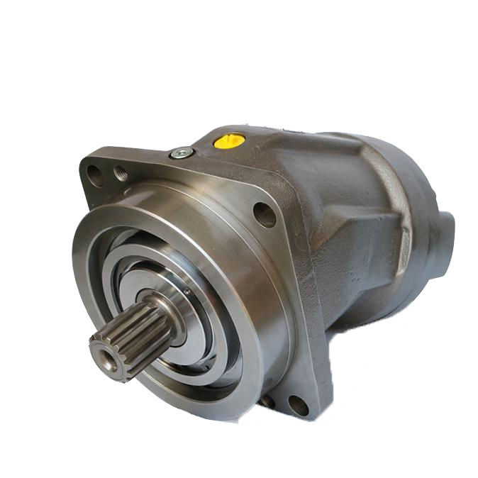
Positive Displacement Pumps
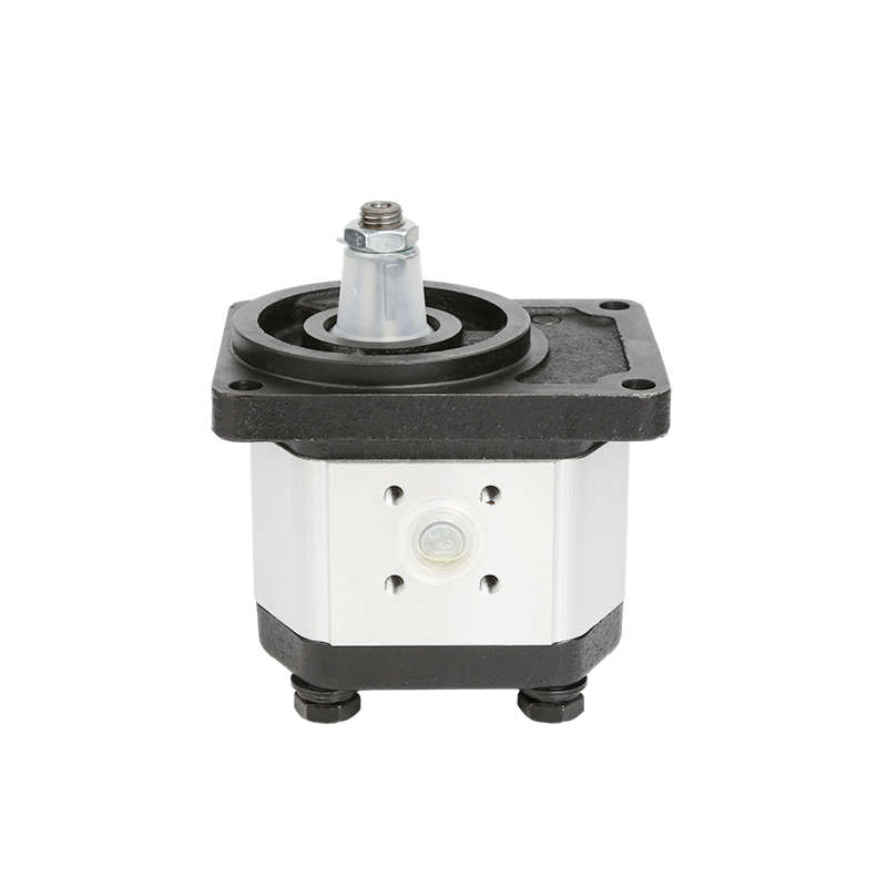
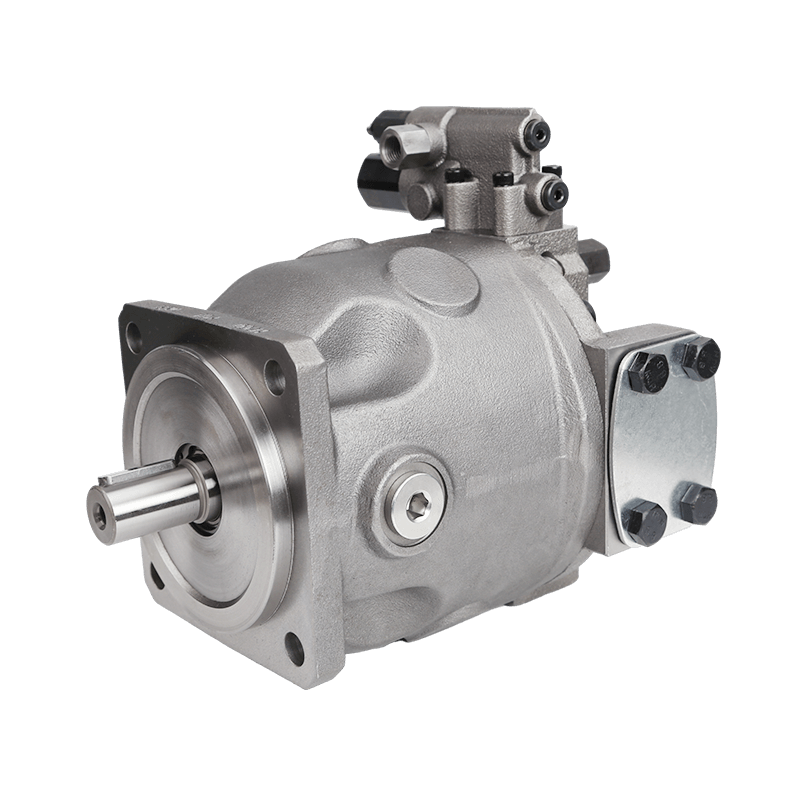
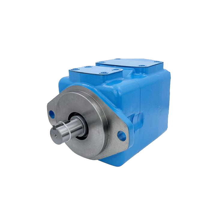
On the other hand, rotary positive displacement pumps—such as gear, vane, and lobe designs—push out an almost steady volume of fluid for each revolution no matter the downstream pressure. When discharge lines get blocked or valves close without warning, pressure climbs quickly. The pump keeps forcing fluid into a tight space. This trait makes relief valves necessary to protect rotary positive displacement pumps and the connected system parts from mechanical harm.
System Design Considerations
Good system design looks at the pump type together with the needs of the application. Systems that have changing loads or possible restrictions gain a lot from relief valve use. Self-regulating kinetic pumps may depend on other safety steps like motor overload protection.
Relief Valve Operation
Pressure relief valves usually use a spring-loaded poppet or spool mechanism. During normal running conditions, the spring force keeps the poppet seated and blocks flow through the valve. As system pressure rises and pushes harder on the poppet face than the spring preload, the poppet lifts. This action lets fluid move around through the valve outlet.
An adjusting screw or similar mechanism presses or loosens the spring to set the cracking pressure. This is the point where the valve starts to open. Full bypass happens when pressure overcomes the spring enough to raise the poppet to its widest opening. Many designs then divert 100% of pump flow. Once pressure falls below the reseat pressure, the spring pushes the poppet back to the closed position. Normal system operation returns.
Different designs come from various manufacturers. Some valves have adjustable settings for changes in the field. Others arrive with fixed factory calibrations. Full-ported designs cut pressure drop during bypass and lower heat buildup. Valve response time, reseat traits, and flow capacity affect overall system performance and protection level directly.
Types of Relief Valves
Hydraulic pressure relief valves appear in several setups made for specific mounting and flow diversion needs.
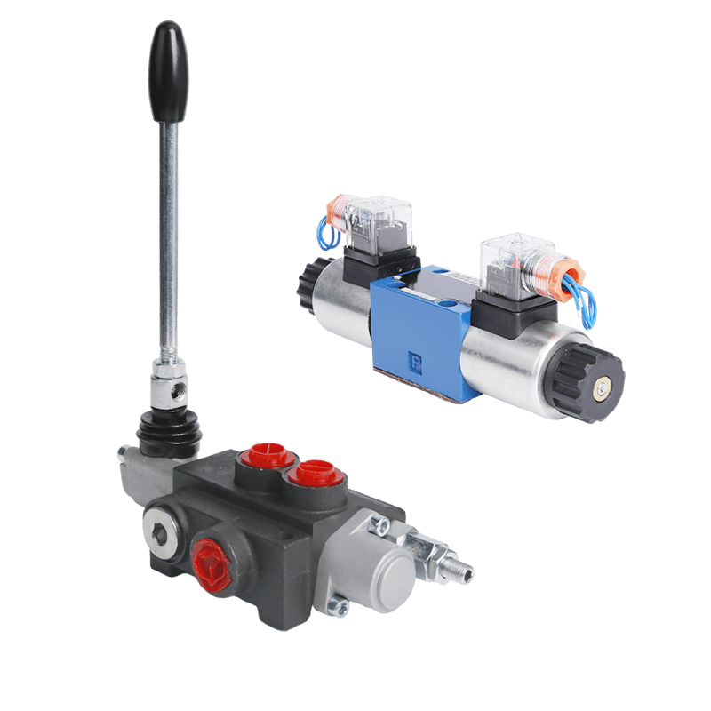
Direct Acting Relief Valves
Direct acting models give fast response through a simple poppet or ball design held by a spring. These valves fit lower flow applications or secondary protection roles because of their small size and quick opening traits. They provide steady performance with little hysteresis in many industrial settings.
Pilot Operated Relief Valves
Pilot operated relief valves manage higher flow rates and pressures in a more efficient way. A small pilot section senses system pressure and controls a larger main stage. This design lowers pressure override—the extra pressure needed for full flow—and gives better stability in high-capacity systems. Models such as Daikin JRB or modular MBP-01 series show pilot-operated technology often used in modern hydraulic circuits.
Modular Relief Valves
Modular or sandwich-style relief valves mount straight onto directional control valves or manifolds. These space-saving designs fit well into stacked valve assemblies. They reduce piping and possible leak points. Brands like POOCCA offer modular relief options that work with standard hydraulic systems.
Cartridge Relief Valves
Thread-in cartridge valves fit into machined cavities inside manifolds or custom blocks. Their compact shape supports high-pressure applications and allows easy replacement plus system customization. Cartridge styles show up often in mobile machinery and compact power units.

Internal vs. External Mounting Configurations
Internal relief valves mount directly on or inside the pump housing. They bypass fluid from outlet back to inlet inside the pump. This setup saves space and removes external piping. Yet it can create heat during long bypass periods.
External or return-to-tank relief valves send flow back to the reservoir. This allows heat to spread out and makes it possible to watch bypass activity. Inline system relief valves install in discharge piping after the pump. They give wider circuit protection.
Pressure Control Valves in Hydraulic Systems
Pressure relief valves make up one part of a larger group of pressure control valves. These include pressure reducing valves, sequence valves, counterbalance valves, and unloading valves. Each one has its own job while it adds to overall system stability.
Pressure reducing valves keep a lower steady pressure in a secondary circuit no matter the higher primary pressure. Sequence valves control the order of actuator operation by opening at preset pressures. Counterbalance valves stop loads from falling without control in vertical uses.
Applications of Pressure Relief Valves in Hydraulic Systems
Pressure relief valves see wide use across different sectors.
- In construction equipment, they protect hydraulic excavators, loaders, and cranes from pressure spikes caused by loads.
- Agricultural machinery depends on relief valves to guard implements during sudden stops or changes in soil resistance.
- Mining operations use strong relief solutions in high-vibration and high-dust settings, where equipment reliability affects output directly.
- Industrial presses, injection molding machines, and material handling systems add relief valves to hold precise pressure control and avoid overload situations.
Mobile hydraulics need compact, high-flow relief valves that can handle shock loads and temperature changes. Fixed industrial installations often choose pilot-operated models for large flow capacities and steady performance over long duty cycles.
Selection Criteria for Pressure Relief Valves
Choosing the right pressure relief valve calls for careful review of several technical points.
Pressure Ratings and Set Pressure
The valve must handle the system’s maximum operating pressure plus a safety margin. Set pressure should match the lowest rated component in the circuit. This ensures protection without frequent false trips.
Flow Capacity
Valve sizing must manage the full pump output flow at the relieving pressure with acceptable pressure override. Valves that are too small lead to extra pressure buildup before full bypass and reduce safety.
Fluid Compatibility
Seal and body materials need to match the hydraulic fluid type, viscosity range, and operating temperature. Special attention goes to fire-resistant fluids, biodegradable oils, or extreme temperature uses.
Response Time and Stability
Fast opening helps systems that face shocks. Stable reseat behavior prevents chatter or instability. Pilot-operated designs often perform well in applications that need small pressure changes.
Mounting and Installation Space
Available space, port sizes, and manifold compatibility decide whether cartridge, modular, inline, or pump-mounted styles work best.
Other points include adjustment method, tamper resistance, certification needs, and environmental protections such as corrosion resistance.
Installation Best Practices for Pressure Relief Valves
Correct installation brings out the best valve performance and system safety.
- Valves should mount as close as possible to the pump outlet for main protection.
- Inlet piping diameter must equal or exceed the valve port size to stop flow restriction.
- Orientation follows manufacturer guidelines—often vertical for many models—to support proper poppet function and drainage.
- Return-to-tank lines need enough size and proper routing to avoid backpressure that could change valve performance.
- Installers should avoid isolation valves upstream of system relief valves, as accidental closure removes protection.
- Multiple relief points can help complex circuits with long piping runs or several actuators.
Partner with a Trusted Hydraulic Valve Manufacturer and Supplier
Equipment manufacturers, OEMs, distributors, and system integrators who look for high-quality pressure relief valves and complete hydraulic valve solutions gain from working directly with an established factory. POOCCA delivers competitive factory pricing, consistent quality, broad product availability, and professional technical assistance for hydraulic pressure control components. Reach out today to discuss specific requirements, request catalogs, or obtain quotations for pressure relief valves and related hydraulic products.
FAQ
What is the primary function of a pressure relief valve in a hydraulic system?
Pressure relief valves protect the system by opening to divert excess fluid when pressure exceeds the set limit. They prevent damage to pumps, hoses, and other components.
What are the main types of hydraulic pressure relief valves?
Common types include direct acting, pilot operated, modular, cartridge, internal pump-mounted, and inline/return-to-tank configurations. Each offers distinct advantages in flow capacity, response, and installation.