
 English
 Russian
 Arabic
 Indonesian
 Turkish
 Vietnamese
 Polish
 German
 Malay
Malay Thai
Thai Kazakh
 Spanish
 Chinese (Simplified)
 Korean
 Italian
 Azerbaijani
 Dutch
Dutch French
 Romanian
 Portuguese
 Hindi
HindiA hydraulic pump operates as part of a complete circuit that stores and conditions fluid, controls pressure and flow, moves an actuator, and returns or recirculates the fluid.
Understanding hydraulic pump circuits is important when selecting a replacement pump, troubleshooting unstable operation, or comparing open- and closed-circuit designs. A pump may fit the mounting interface but remain unsuitable for the circuit’s flow direction, control method, inlet conditions, or operating duty.
This guide explains the main fluid paths, components, and selection considerations in open and closed hydraulic circuits.
What Is a Hydraulic Pump Circuit?
A hydraulic pump circuit is a group of interconnected components that transmit and control power through hydraulic fluid.
The hydraulic pump converts mechanical power into hydraulic power by supplying flow against the pressure required by the load and circuit losses. Valves direct and regulate that flow, while cylinders or hydraulic motors convert hydraulic power into mechanical movement.
A typical circuit may include:
- A hydraulic reservoir
- A prime mover
- A hydraulic pump
- Pressure-control valves
- Directional-control valves
- Flow-control valves
- Hydraulic cylinders or motors
- Filters
- Hoses, pipes, and fittings
- A cooler or heat exchanger
- Pressure and temperature monitoring devices
The arrangement depends on the machine and its functions. An industrial cylinder circuit may use a fixed-displacement pump and directional valve. A mobile hydrostatic transmission may use a variable-displacement pump and motor in a closed loop.
The Pump’s Role in the Circuit
The pump supplies flow to the hydraulic system. System pressure develops according to the actuator load, valve settings, line resistance, and other circuit losses.
Pump selection therefore involves more than checking a maximum pressure rating. The designer or replacement buyer should confirm:
- Required flow
- Pump displacement
- Input speed
- Rotation direction
- Fluid type and viscosity
- Inlet conditions
- Control method
- Duty cycle
- Actuator requirements
- Circuit configuration
Insufficient pump flow may cause slow actuator movement. Excessive flow may increase throttling losses, heat generation, noise, and input-power demand when the circuit cannot use the additional output efficiently.
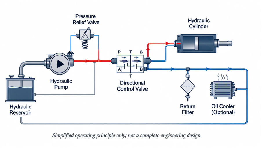
How an Open Hydraulic Circuit Works
In a typical open circuit, the pump draws fluid from a reservoir and sends it into the pressure line. The fluid passes through the required control valves, performs work at a cylinder or hydraulic motor, and returns to the reservoir.
The simplified flow path is:
Reservoir → Pump → Pressure Protection → Control Valve → Actuator → Return Line → Reservoir
The reservoir stores hydraulic fluid and supports cooling, air separation, contamination management, and pump inlet supply. Depending on the application, an open circuit may use a fixed- or variable-displacement pump.
Common open-circuit features include:
- A pump inlet connected to the reservoir
- A pressure line supplying the control system
- A return line leading to the reservoir
- Pressure-control and directional-control functions
- Filtration at locations selected for the circuit
- One or more cylinders or hydraulic motors
When the directional valve changes position, it routes flow toward the required actuator port. Fluid leaving the actuator returns through the return side of the circuit.
Excessive inlet restriction or unsuitable viscosity can reduce inlet pressure and promote cavitation. Suction-line air leaks or air entrainment at the reservoir can cause aeration. Both conditions may produce noise, unstable operation, and component damage.
Open Circuit Is Not the Same as Open Center
Open circuit and open center are not interchangeable terms.
Open or closed circuit describes the main fluid return path. Open or closed center describes the flow connections through a directional valve when the valve is in its neutral position and relates to how pump supply is controlled.
An open-circuit hydraulic system can use closed-center valves. The circuit classification and valve-center configuration should therefore be checked separately.
How a Closed Hydraulic Circuit Works
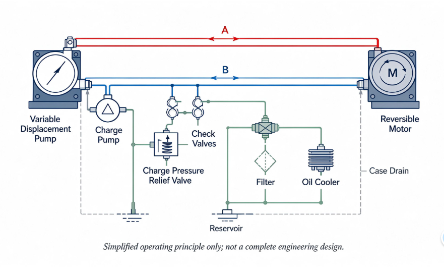
In a typical closed hydrostatic circuit, the main pump ports connect directly to the main ports of a hydraulic motor. Fluid leaving the pump travels to the motor and then returns directly to the pump instead of returning to the reservoir after every pass.
The simplified main-loop path is:
Main Pump → Hydraulic Motor → Main Pump
In a reversible closed-circuit drive, either main line can operate at high pressure. The pressure relationship depends on both the direction of motion and whether the hydraulic unit is driving the load or being driven by it, such as during braking or overrunning conditions.
Flow direction and high-pressure side should therefore not be treated as the same concept. During deceleration, downhill travel, or another load-driven condition, the direction of power transmission may change even when the machine continues moving in the same direction.
The main loop also requires supporting functions that are not represented by the simplified pump-and-motor path. Depending on the design, these may include:
- A charge supply
- Charge-pressure control
- Case-drain lines
- Flushing or hot-oil exchange
- Filtration
- Cooling
- Loop-pressure protection
- A reservoir sized for the charge circuit, fluid conditioning, and application requirements
Internal leakage and fluid removed for cooling or flushing must be replenished. A charge supply feeds the low-pressure side of the loop and helps maintain the inlet conditions required by the hydrostatic units.
The charge source may be an integral charge pump or a suitably designed external supply. The exact arrangement must be confirmed from the circuit and product documentation.
Typical Closed-Circuit Applications
Closed circuits are commonly used in hydrostatic drives where a pump powers a hydraulic motor. Examples may include mobile travel drives, winches, conveyors, and other rotary systems requiring controlled speed, torque, or reversal.
The circuit should not be selected only because closed-loop packaging appears compact. Control response, cooling, charge flow, filtration, case pressure, operating environment, braking behavior, and service requirements must also be evaluated.
Open Circuit vs. Closed Circuit
| Selection Factor | Open Circuit | Closed Circuit |
|---|---|---|
| Main fluid path | Reservoir to pump, actuator, and reservoir | Pump to motor and directly back to pump |
| Common actuator use | Cylinders and hydraulic motors | Primarily hydrostatic motor drives |
| Reservoir connection | Main return flow enters the reservoir | Main loop recirculates; support circuits connect to a reservoir |
| Reversal | Commonly controlled by directional valves | Often controlled by varying pump displacement through neutral |
| Makeup fluid | Supplied through the reservoir and pump inlet | Supplied by a charge or replenishing source |
| Cooling | Return flow may pass through a cooler and reservoir | Often uses flushing or hot-oil exchange |
| Supporting functions | Reservoir, valves, filters, and return system | Charge supply, case drains, filtration, cooling, and loop protection |
| Selection focus | Multiple-function control and actuator demands | Hydrostatic drive behavior, braking, and bidirectional control |
Neither arrangement is universally preferable. The correct choice depends on the actuator, load behavior, required control, available space, duty cycle, cooling capacity, and maintenance requirements.
Important Hydraulic Circuit Components
Reservoir
The reservoir stores and conditions usable hydraulic fluid. Its required capacity depends on heat rejection, deaeration, contamination control, fluid-level changes, charge-flow requirements, and any circuits sharing the same fluid supply.
Pressure-Relief Valve
A pressure-relief valve limits circuit pressure according to the system design. It should not be treated as a normal flow-control device unless the circuit was designed for that operating condition.
Continuous flow across a relief path can waste input power and generate excessive heat.
Directional-Control Valve
A directional-control valve determines where fluid travels. It can start, stop, or reverse actuator movement by connecting pressure and return paths to different ports.
For more information, see Kamchau’s guide to directional-control valves and hydraulic flow.
Flow-Control Valve
A flow-control valve regulates fluid reaching an actuator. Restricting flow can control actuator speed, but the associated pressure drop converts hydraulic power into heat. The circuit must account for this energy loss.
Filters
Filters remove contamination that can damage pumps, valves, motors, and cylinders. Filter location and rating should match the required cleanliness, allowable pressure drop, fluid viscosity, cold-start conditions, and circuit layout.
Hydraulic Actuator
A cylinder converts hydraulic power into linear force and movement. A hydraulic motor produces rotary torque and speed.
Actuator load and speed requirements influence the pressure and flow that the pump circuit must provide.
How to Read a Basic Hydraulic Circuit Diagram
A hydraulic schematic represents component functions and connections. It does not necessarily reproduce the physical layout of the machine.
Use the following sequence when reading a basic diagram:
- Locate the reservoir or closed-loop main lines.
- Identify the pump and its drive source.
- Follow the line leaving each pump port.
- Locate pressure-control components.
- Identify directional and flow-control valves.
- Trace the lines to the cylinder or motor.
- Follow the return or low-pressure path.
- Locate filters, coolers, drains, pilot lines, and test points.
- Check the documented neutral and commanded valve positions.
- Compare the schematic with the actual installed circuit.
Do not assume that two crossing lines are connected. Hydraulic diagrams use specific junction symbols to distinguish connected lines from lines that merely cross.
Previous repairs or modifications may cause the installed system to differ from an older manual. Any discrepancy should be resolved before selecting components or diagnosing operation.
Safety Before Hydraulic Troubleshooting
Before opening any hydraulic connection, stop the machine, isolate energy sources, mechanically support raised loads, and release and verify stored hydraulic pressure, including accumulator pressure, according to the manufacturer’s procedure.
Never loosen a pressurized connection or use your hands to locate a hydraulic leak. Testing on an operating system should be performed by qualified personnel using instruments, hoses, and fittings rated for the applicable pressure and following the manufacturer’s test procedure.
Common Hydraulic Pump Circuit Problems
Low or Unstable Flow
Possible causes include inlet restriction, aeration, unsuitable fluid viscosity, incorrect pump speed, internal leakage, an incorrect control signal, or a variable pump that is not reaching the commanded displacement.
Excessive Heat
Heat may result from continuous pressure drop, relief-valve flow, undersized lines, excessive internal leakage, unsuitable viscosity, inadequate cooling, or a mismatch between pump output and system demand.
Abnormal Noise
Noise may indicate cavitation, aeration, mechanical misalignment, contamination, unstable controls, bearing damage, or another mechanical problem. Cavitation and aeration can produce similar symptoms but have different causes and should be investigated separately.
Pressure Without Actuator Movement
A high pump-outlet pressure does not confirm that sufficient pressure differential or usable flow is available at the actuator.
The measured result must be interpreted using the hydraulic schematic, specified test points, valve commands, actuator load, and operating condition. Possible causes include a blocked flow path, an incorrectly positioned valve, excessive load, actuator leakage, or inadequate usable flow.
A single pressure reading should not be used to conclude that the pump or actuator has failed.
Repeated Pump Failure
A replacement pump may fail again when the original circuit problem remains unresolved. Before installing another pump, inspect filtration, fluid condition, inlet plumbing, relief settings, alignment, cooling, case-drain routing, actuator condition, and the cause of the previous failure.
See Kamchau’s hydraulic pump failure diagnosis guide for a more detailed troubleshooting sequence.
Questions to Ask Before Selecting a Pump
Before requesting a new or replacement pump, confirm:
- Is the system open circuit or closed circuit?
- Does the pump operate a cylinder, motor, or multiple functions?
- What flow is required at the actual input speed?
- What are the normal and peak operating pressures?
- Is the pump fixed or variable displacement?
- What pump control is required?
- What is the correct rotation direction?
- What mounting flange, shaft, and port configuration are needed?
- Are charge, case-drain, pilot, or load-sensing connections present?
- What fluid and operating-temperature range apply?
- What caused the previous pump to be removed?
Use the machine manual, hydraulic schematic, nameplate, confirmed drawings, and measured operating data when available. Do not infer missing specifications from the appearance of the pump.
Frequently Asked Questions
What is a hydraulic pump circuit?
It is an interconnected system in which the pump supplies hydraulic flow, valves control the flow and pressure, and cylinders or motors convert hydraulic power into mechanical movement.
What is the main difference between open and closed hydraulic circuits?
In an open circuit, fluid leaving the actuator normally returns to a reservoir. In a closed hydrostatic circuit, the main flow returns directly from the hydraulic motor to the main pump.
Is an open circuit the same as an open-center valve system?
No. Open or closed circuit describes the main fluid path. Open or closed center describes the connections through a directional valve in its neutral position.
Can the same pump be used in open and closed circuits?
Not automatically. Construction, controls, inlet requirements, charge functions, porting, case-drain limits, and the approved circuit type must be verified using the applicable product documentation.
Why does a typical closed-circuit hydrostatic drive need a charge supply?
The charge supply replenishes leakage and flushing flow and maintains the required low-side pressure. Depending on the design, it may also supply control functions. Charge flow may come from an integral charge pump or a suitably designed external source.
Why does a hydraulic circuit overheat?
Possible causes include excessive pressure drop, continuous relief flow, internal leakage, unsuitable fluid viscosity, restricted plumbing, inadequate cooling, or a mismatch between pump output and system demand.
Evaluate the Complete Circuit Before Selecting a Pump
Reliable pump selection begins with the complete hydraulic circuit. The circuit configuration, actuator, flow requirement, pressure demand, load behavior, control method, inlet conditions, and cooling arrangement all affect pump suitability.
When requesting assistance from Kamchau, provide the pump model, hydraulic schematic, machine information, operating pressure and flow, fluid type, photographs, and a description of the current problem. Kamchau can help review the available information and compare appropriate hydraulic pump options.
Final pump selection, system testing, and installation should follow the applicable manufacturer documentation and be completed by qualified personnel.