
 English
 Russian
 Arabic
 Indonesian
 Turkish
 Vietnamese
 Polish
 German
 Malay
Malay Thai
Thai Kazakh
 Spanish
 Chinese (Simplified)
 Korean
 Italian
 Azerbaijani
 Dutch
Dutch French
 Romanian
 Portuguese
 Hindi
Hindi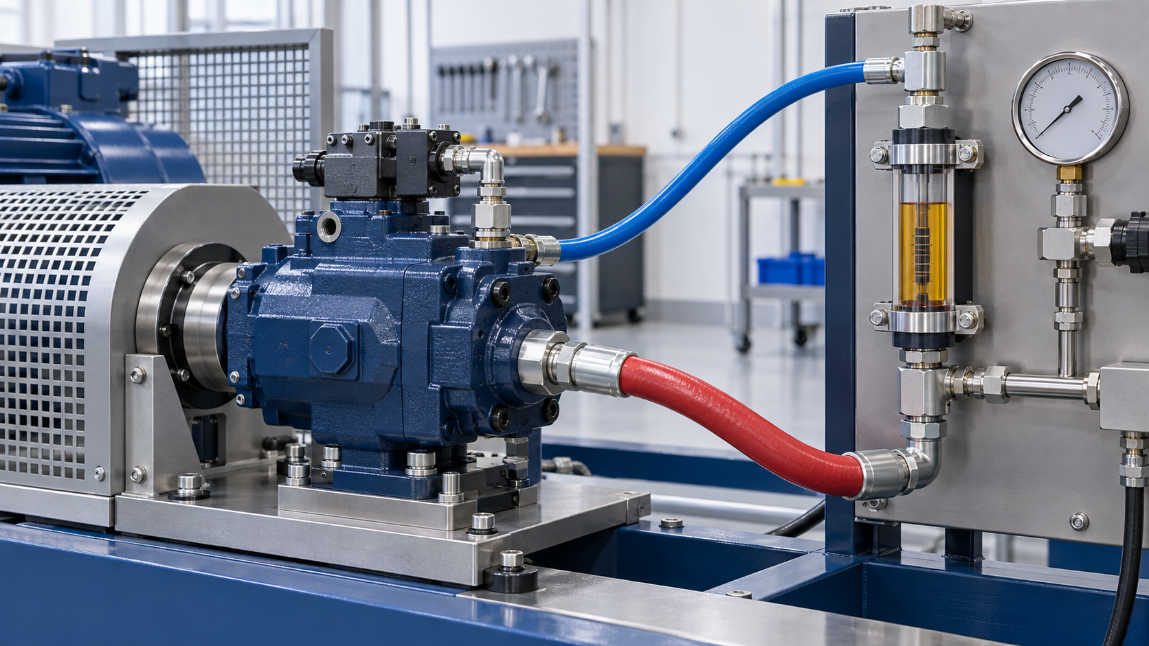
High case-drain flow can indicate internal leakage in a hydraulic pump, but one measurement is not enough to justify a replacement. Drain flow changes with pump design, displacement, pressure, speed, oil viscosity, temperature, and control condition. A reading that appears high on one machine may be normal for another pump series.
A useful hydraulic pump case drain flow test therefore does more than collect oil in a container. It records the operating condition, protects the pump housing from backpressure, compares the result with model-specific data, and checks whether other faults could be producing the same symptoms. This guide explains a practical sequence for procurement teams, maintenance technicians, and engineers evaluating a suspect piston pump. When the machine has several symptoms, begin with a broader hydraulic pump failure diagnosis before isolating the case-drain circuit.
What Case-Drain Flow Tells You
Inside a piston pump, small clearances allow lubricating and cooling leakage between moving parts. That oil enters the housing and leaves through the case-drain connection. Some leakage is expected; a perfectly sealed rotating group would not operate correctly.
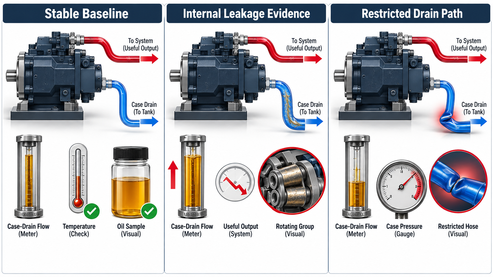
As clearances increase through wear or damage, more oil may bypass internally. Rising case-drain flow can therefore support a diagnosis of rotating-group wear. It can also help explain reduced output flow, slower actuator movement, excess heat, or a pump that can no longer maintain performance under load.
However, case-drain flow is evidence, not a complete diagnosis. A valid assessment should answer four questions:
- Was the pump tested at a defined speed, displacement, pressure, and oil temperature?
- Was the drain path unrestricted and connected according to the pump documentation?
- Does the manufacturer publish an allowable value or test condition for the exact model?
- Do pressure, flow, noise, temperature, and contamination findings support the same conclusion?
If the available product documentation does not specify a case-drain limit, record: “Not specified in the available product documentation.” Establishing a trend from known-good operation is safer than inventing a pass/fail number.
Safety Before the Test
Hydraulic testing can expose personnel to hot oil, high-pressure injection hazards, moving machinery, and stored energy. Before opening any connection, stop the machine, isolate its energy sources, mechanically support raised loads, discharge accumulators, and verify that stored hydraulic pressure has been released according to the machine manufacturer’s procedure. Never use a hand to search for a leak.
Running measurements should be performed only by qualified personnel using properly rated hoses, fittings, guards, and instruments. The test arrangement must not block the drain line or raise pump housing pressure beyond the model-specific limit.
A Practical Case-Drain Test Procedure
1. Confirm the Correct Drain Port and Routing
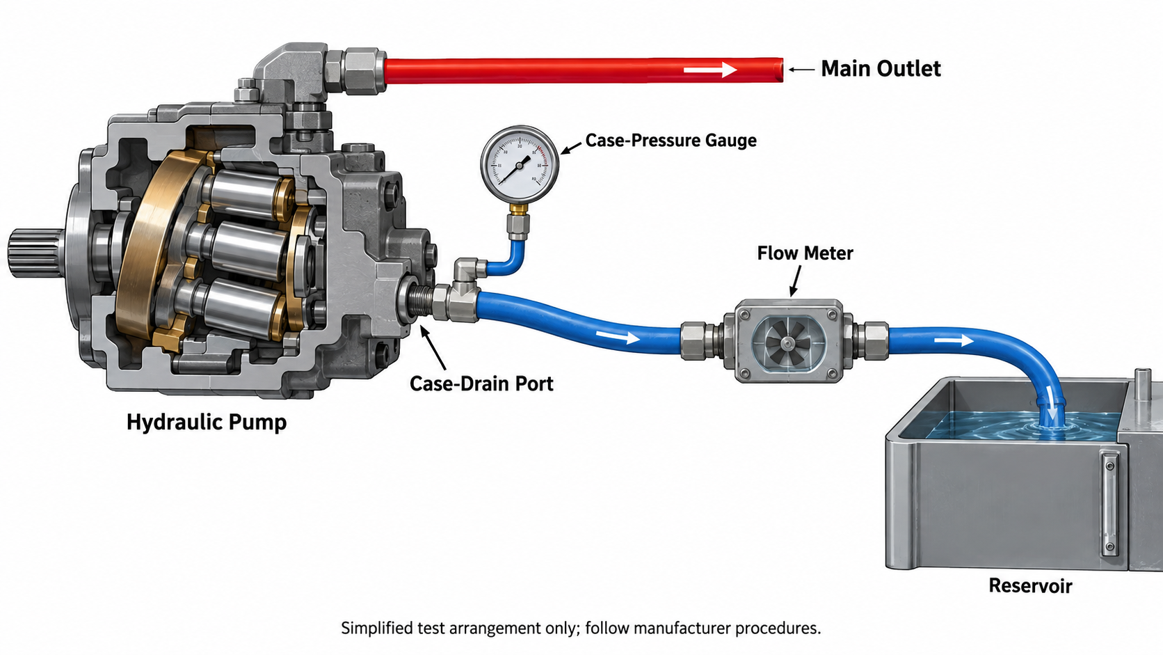
Use the pump drawing or service documentation to identify the designated case-drain port. On pumps with multiple drain ports, installation orientation may determine which port should be used. Confirm whether the housing requires a separate filling or venting procedure before startup.
Trace the complete drain line to the reservoir. Look for closed valves, incorrect tees, undersized replacement fittings, kinked hose, damaged quick couplers, clogged filters, or a return connection located where reservoir pressure can rise. A restricted line can create harmful housing pressure and distort the test.
2. Choose a Suitable Measurement Method
A properly rated inline flow meter is generally the most controlled option. A timed-volume test may be permitted by an equipment procedure, but it needs safe containment, correct hose restraint, and careful control of temperature and splash risk. Do not improvise with unapproved tubing or an open container near rotating equipment.
The meter and temporary plumbing must have enough flow capacity to avoid creating backpressure. If case pressure is also measured, use an instrument with an appropriate range and connect it at a manufacturer-approved location.
3. Bring the System to a Defined Temperature
Cold oil can produce a misleading result because viscosity affects leakage and drain pressure. Warm the system using the machine maker’s normal procedure and record the stabilized temperature. Do not heat the system by holding a relief valve open unless the manufacturer specifically permits that method.
If the symptom occurs only during cold start or only after extended operation, capture separate readings under those clearly labeled conditions. Do not combine them into one average.
4. Record a Baseline at Low Load
With the system in a safe, specified low-load condition, record speed, system pressure, oil temperature, case-drain flow, and case pressure. Observe the drain stream or meter behavior for pulsing, foam, or sudden fluctuation. Aerated oil can make a volume reading unstable and may point to an inlet or reservoir problem rather than wear alone.
5. Test at the Specified Operating Point
Increase the load only through the approved test procedure. Record the same variables at each operating point. On a variable-displacement pump, note whether it is at full displacement, partially stroked, pressure compensated, or commanded toward neutral. These states can produce different leakage behavior.
Do not assume that maximum system pressure is automatically the correct test point. Follow the pump or machine documentation. If the required condition cannot be created safely, stop and use a qualified hydraulic test facility.
6. Repeat the Reading
Hold each permitted condition long enough for the instrument to stabilize, then repeat the measurement. A repeatable result is more useful than a single peak. If flow climbs rapidly with temperature or pressure, document the rate and the matching operating data.
7. Return the Circuit to Its Approved Configuration
After shutdown and pressure verification, remove temporary equipment, restore the original drain routing, replace disturbed seals as required, and check the oil level. Inspect the restored connections during a controlled restart. If a replacement pump has been installed, follow the machine documentation together with this hydraulic-system restart checklist.
How to Interpret the Result
First compare the measured value with the official limit and test condition for the complete pump code. A limit for another frame size, control option, or product generation is not a reliable substitute.
If no official limit is available, compare the reading with a documented baseline from the same pump model under equivalent conditions. Look for a sustained trend rather than relying on a generic rule such as “a fixed percentage of pump flow.” Universal percentages ignore design differences and can cause a serviceable pump to be rejected—or a damaged one to remain in service.
Interpret related evidence together. Rising drain flow combined with falling delivered flow supports an internal-leakage diagnosis. High case pressure without excessive flow points instead toward a restricted return path. Foam suggests aeration; unusual drain temperature calls for a wider heat-balance check; metallic debris requires contamination control. A normal drain result with poor performance directs attention to the inlet, controls, valves, actuator leakage, or drive speed.
Replacement Decision Checklist
Before ordering a replacement, confirm that you have:
- The full pump model code and readable nameplate photographs
- A repeatable case-drain result with temperature, pressure, and speed recorded
- The applicable manufacturer test limit, if published
- Main pump output-flow and pressure findings
- Case-pressure and drain-line inspection results
- Fluid and filter condition information
- Shaft, flange, rotation, port, and control details for replacement matching
- A plan to flush or clean the affected system if internal damage is confirmed
A replacement pump should solve the verified failure, not simply become the next component exposed to the same root cause.
Frequently Asked Questions
Is some case-drain flow normal in a hydraulic pump?
Yes. Internal leakage lubricates and cools parts of many pump designs. The acceptable amount depends on the exact model and test condition.
Does high case-drain flow always mean the pump must be replaced?
No. Confirm the reading, operating condition, drain routing, case pressure, oil temperature, and manufacturer limit. A restriction or measurement error can mislead the diagnosis.
Can I judge case drain by how fast oil leaves an open hose?
Visual judgment is not a reliable measurement and an open-hose test can be unsafe. Use an approved method and properly rated equipment.
Why does case-drain flow change as the oil warms?
Oil viscosity changes with temperature, affecting internal leakage. That is why temperature must be recorded and controlled when results are compared.
What details should I send when requesting a replacement review?
Send the full model code, nameplate photos, operating pressure and speed, fluid and temperature information, measured drain data, symptoms, and clear photographs of the shaft, flange, ports, and control.
A Better Decision Starts With Comparable Data
A hydraulic pump case drain flow test is most valuable when it is controlled, repeatable, and tied to the exact pump documentation. It can identify internal leakage, reveal a restricted drain path, or show that the fault is probably elsewhere. That evidence helps maintenance teams avoid unnecessary replacement and helps buyers specify the correct configuration.
For a Poocca replacement review, provide the complete model code and the operating data listed above through the Poocca contact page. Compatibility should be confirmed from approved technical information before an order is placed.