According to Grand View Research, the global hydraulic equipment market was valued at more than USD 44 billion in recent years, highlighting how critical hydraulic pumps, motors, valves, and hydraulic cylinders remain across construction, agriculture, manufacturing, and mobile equipment. Within this landscape, the 3 stage hydraulic pump has become an important solution for applications that need compact design, staged pressure increase, stable flow control, and reliable power transmission. For engineers, OEM buyers, and maintenance teams, understanding the working principle of a multi-stage external gear pump is useful not only for selection, but also for system efficiency, safety, and lifecycle cost.
Industry Context: Why the 3 Stage Hydraulic Pump Matters in Modern Hydraulic Systems
The hydraulic industry continues to evolve toward higher efficiency, smaller installation footprints, and more application-specific pump configurations. According to Markets and Markets, the hydraulic pump market is projected to grow at a CAGR of around 5% through the forecast period, driven by demand from industrial machinery, material handling, agricultural equipment, and compact mobile systems. That growth explains why buyers increasingly search not just for a general hydraulic pump, but for specific solutions such as a 3 stage hydraulic pump for mini skid steer, test rigs, or custom hydraulic power units.
A 3 stage hydraulic pump is generally understood as a multi-stage pump architecture in which three gear pumping sections work in sequence or as coordinated sections on a common shaft. In many practical designs, each stage contributes to pressure build-up or flow management. Compared with a single large-displacement pump, a staged design can improve packaging flexibility, distribute hydraulic loading, and support more refined control in systems where pressure stability is essential. According to NFPA data frequently referenced in hydraulic system design discussions, fluid power technologies account for a substantial share of industrial power transmission because of their high force density and controllability. That is especially relevant where hydraulic cylinders must move heavy loads under controlled PSI ranges.
From a commercial perspective, buyers are also more data-driven than ever. According to Statista, global construction machinery sales have shown multi-year resilience despite cyclical fluctuations, reinforcing demand for dependable pumps in OEM supply chains. In practical terms, that means purchasers increasingly ask for documented quality systems, pressure ratings, displacement ranges, and compliance details such as ISO 9001 manufacturing controls and CE marking for applicable export markets.
This is where a supplier like POOCCA can offer a clear advantage. Rather than treating the 3 stage hydraulic pump as a generic catalog item, POOCCA aligns product supply with custom solutions, factory-direct pricing, and flexible MOQ requirements that matter to OEMs and distributors. For buyers comparing brands, the real issue is not only whether a pump can reach a target pressure such as 2,500 to 3,000 PSI, but whether it can do so with repeatable efficiency, controllable leakage, and consistent production quality.
In short, the rising interest in multi-stage gear pumps comes from a mix of technical and commercial realities: compact systems need more pressure capability, buyers need better lifecycle value, and machine builders need suppliers that can support customized hydraulic pumps, valves, motors, and related fluid power components with dependable lead times.

Technical Deep Dive: How a 3 Stage Hydraulic Gear Pump Works
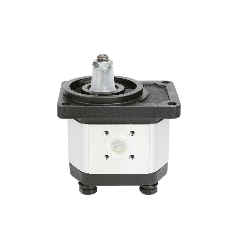
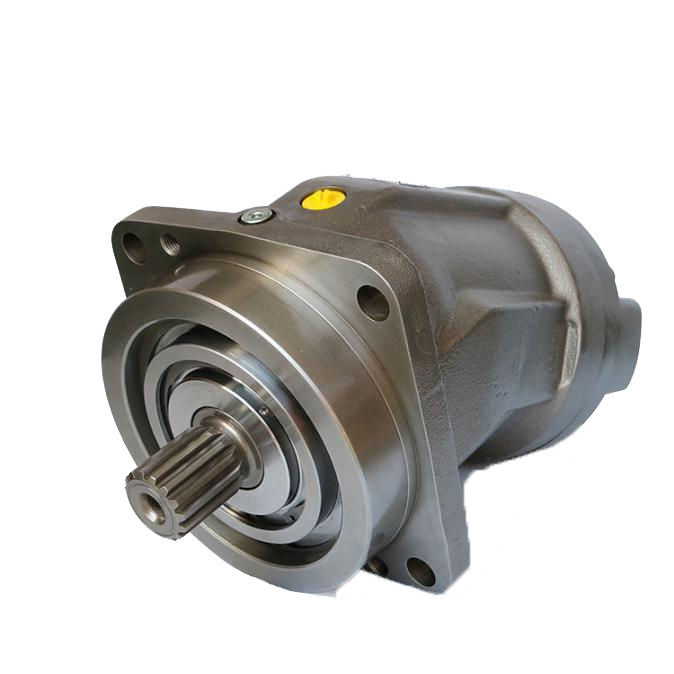
At the core of the 3 stage hydraulic pump working principle is the same basic mechanism used by an external gear pump: meshing gears rotate inside a close-tolerance housing, creating expanding cavities at the inlet that draw in hydraulic fluid, then carrying that fluid around the casing to the outlet where meshing teeth force the fluid into the discharge line. In a multi-stage arrangement, three pumping sections are integrated to achieve staged pressurization, flow management, or both, depending on the circuit design.
As Erik Rydberg, fluid power engineering author and industry expert, states: “Hydraulic pumps create flow, while resistance in the system creates pressure.” That quote is important because it corrects a common misunderstanding. A 3 stage hydraulic pump does not magically produce pressure on its own; instead, it produces flow through three coordinated gear sections, and system resistance from valves, actuators, and load demand determines the pressure rise. In many applications, the stages are arranged so that the fluid experiences progressive energy transfer, allowing the system to reach higher useful pressure than a basic single-stage concept can deliver in the same compact footprint.
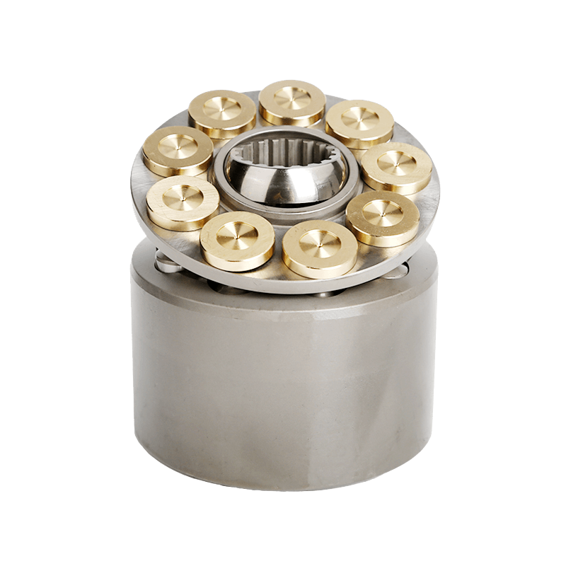
Structurally, a typical 3-stage external gear pump includes a pump body, three gear sets, a shared shaft or coordinated drive system, bearings, end covers, seals, and interstage passages. Each stage must maintain tight internal clearances because leakage between gear tooth tips, side plates, and housing walls directly reduces volumetric efficiency. According to SAE International technical guidance on hydraulic component design, internal leakage and contamination control are major factors affecting pump efficiency and service life. Even a small increase in internal clearance can reduce output consistency at high pressure.
In performance terms, engineers often evaluate a 3 stage hydraulic pump using several key metrics:
- Pressure rating: often discussed in PSI; many industrial gear pump systems operate in the 2,000-3,500 PSI range depending on design.
- Flow rate: measured in GPM; application requirements may range from low-flow precision circuits to higher-flow mobile hydraulic power packs.
- Volumetric efficiency: affected by internal leakage, oil viscosity, and wear.
- Mechanical efficiency: influenced by friction, bearings, shaft loading, and lubrication quality.
- Noise and pulsation: relevant in compact machinery and enclosed power units.
According to ISO guidance used across fluid power manufacturing, contamination is one of the leading causes of hydraulic component failure, and some industry sources estimate that over 70% of hydraulic failures are related to fluid contamination or poor maintenance practices. That matters even more in multi-stage pumps because contamination can damage more than one pumping section, accelerating wear across the entire assembly. According to IBISWorld, industrial maintenance spending remains a major operational priority as manufacturers seek to reduce downtime and improve equipment utilization. For buyers, that translates into one practical truth: the best pump is not simply the highest-pressure pump, but the one whose design, sealing, and production consistency reduce total cost of ownership.
As Brendan Casey, hydraulic systems consultant, states: “Most hydraulic problems are caused by heat, contamination, and improper maintenance rather than by defective design alone.” In a 3 stage pump, heat generation can rise if the system is oversized, fluid viscosity is wrong, or valves create constant throttling losses. Poor suction conditions can also cause cavitation, which damages gear tooth surfaces and reduces output. That is why identifying the inlet and outlet correctly, matching rotation direction, and verifying line sizing are essential for installation.
For OEMs and distributors that need a balance of technical reliability and commercial flexibility, POOCCA offers practical value through custom hydraulic pump configurations, coordinated supply of pumps, valves, motors, and components, and factory-direct support. That can be especially useful for applications needing specific displacement combinations, mounting patterns, or export documentation.
Industry Standards and Compliance: ISO, SAE, NFPA, CE, and API Considerations
When evaluating a 3 stage hydraulic pump, standards and certifications are not secondary details; they are part of the purchase decision. In B2B procurement, a pump must fit the application technically, but it must also align with quality systems, safety expectations, and market access requirements. One of the most important foundations is ISO 9001, which provides a structured quality management framework. A manufacturer operating under ISO 9001 principles is expected to maintain documented processes, traceability, corrective action procedures, and continuous improvement systems. For hydraulic pumps, this often translates into more stable machining tolerances, better inspection discipline, and more consistent performance from batch to batch.
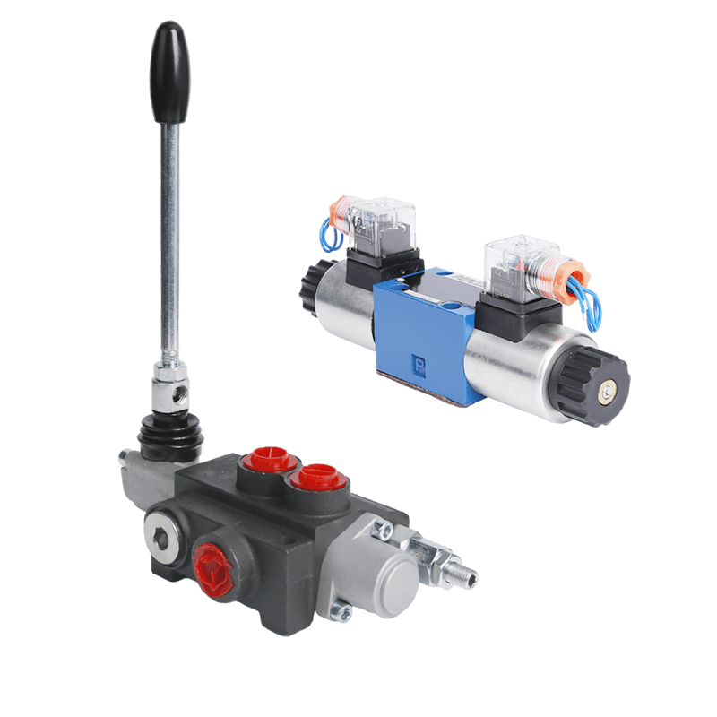
According to ISO, standardization improves interoperability, quality consistency, and international trade efficiency across industrial products. For hydraulic buyers, that consistency matters because a pump is rarely a standalone purchase. It must integrate with hydraulic cylinders, directional valves, relief valves, hydraulic motors, manifolds, hoses, and filtration systems. In a multi-stage pump, dimensional consistency is even more important because interstage sealing, housing alignment, and shaft accuracy directly influence leakage and efficiency.
SAE International also plays a central role in the fluid power sector through terminology, test methods, and engineering guidance. SAE standards help define how hydraulic components are specified and compared, which is critical when buyers evaluate displacement, shaft options, pressure capability, port configurations, and mounting interfaces. Meanwhile, the National Fluid Power Association (NFPA) contributes valuable reference frameworks for system design and fluid power education. According to NFPA industry resources, proper specification and maintenance of fluid power systems can significantly reduce downtime and improve energy utilization in industrial environments.
In export-oriented business, CE marking may also be relevant depending on the final equipment configuration and destination market. While a hydraulic pump itself may be part of a larger machine compliance pathway, buyers often prefer suppliers familiar with documentation, materials declarations, and conformity support. In sectors tied to energy, process systems, or heavy industrial operation, API standards may additionally influence material, sealing, or performance expectations depending on end use.
From an engineering standpoint, standards support three practical decisions. First, they help verify whether the pump can withstand required pressure ranges without premature wear. Second, they provide a basis for comparing suppliers beyond marketing claims. Third, they reduce procurement risk in multi-country supply chains. According to Markets and Markets, industrial automation and machine modernization are key growth drivers for hydraulics, and standardized, documented components are increasingly favored in global sourcing.
For companies seeking a supply partner rather than a one-off vendor, POOCCA fits this standards-driven environment by connecting custom solutions with quality-focused manufacturing, flexible MOQ, and responsive communication for B2B projects. That is especially useful when customers need to align pressure, GPM, mounting dimensions, and compliance documentation in one procurement cycle.
Implementation Guide: Selection, Installation, Maintenance, and Common Mistakes
Selecting the right 3 stage hydraulic pump starts with the application, not the catalog. Buyers should define required flow in GPM, target working pressure in PSI, duty cycle, oil viscosity range, ambient conditions, and actuator demand. For example, a mini skid steer, compact power unit, or industrial test stand may all use a multi-stage gear pump, but their flow stability, noise tolerance, and pressure duty can differ significantly. According to Statista, machinery operators continue to prioritize uptime and maintenance efficiency, which means component selection has direct operational consequences.
A practical implementation checklist includes:
- Confirm rotation direction before startup. Running a hydraulic gear pump backwards can starve lubrication zones, reverse inlet/outlet function, and cause rapid seal or gear damage.
- Identify inlet and outlet ports correctly. The inlet is typically the larger, lower-pressure port; the outlet is the pressurized discharge side. Manufacturer markings should always be verified.
- Match pump displacement to system demand. Oversized pumps create heat and throttling losses; undersized pumps reduce actuator speed and efficiency.
- Protect suction conditions. Poor inlet line design can cause cavitation, aeration, and unstable output.
- Use proper filtration to limit contamination-related wear.
According to NFPA educational resources, poor fluid cleanliness and improper installation remain among the most common causes of hydraulic reliability issues. According to ISO cleanliness principles used in hydraulic maintenance, contamination control can dramatically improve component lifespan. In real-world terms, a well-filtered, properly aligned pump can deliver far better service life than a premium pump installed with undersized suction lines or dirty oil.
Maintenance should focus on pressure trend monitoring, case noise changes, leakage inspection, fluid analysis, and temperature control. If a pump begins losing pressure, engineers should check relief valve settings, wear-related internal leakage, shaft seal condition, and interstage sealing integrity. If the pump becomes noisy, inspect for cavitation, inlet restrictions, air ingestion, or bearing wear. If output becomes unstable, review fluid condition, viscosity, and whether the gears are experiencing side-plate wear.
According to IBISWorld, downtime costs continue to rise for industrial operators, making preventive maintenance more valuable than reactive repair. Even a small hydraulic system outage can disrupt a full production cell or disable a mobile machine in the field. For that reason, many OEMs now prefer suppliers that can support repeat orders, component matching, and model customization rather than offering only standard stock units.
This is another reason POOCCA stands out in practical implementation. Its value proposition goes beyond selling a gear pump: it supports customers looking for custom specifications, coordinated sourcing, factory-direct pricing, and flexible MOQ for both development projects and production orders. For distributors and machine builders, that can shorten sourcing cycles and reduce mismatch risk during product selection.
Future Outlook: Market Demand, Efficiency Trends, and Smarter Pump Selection
The future of the 3 stage hydraulic pump will be shaped by three forces: equipment compactness, higher efficiency expectations, and global sourcing discipline. According to Grand View Research, industrial equipment buyers increasingly prioritize energy-efficient and durable hydraulic components as part of broader modernization initiatives. According to Markets and Markets, demand growth in agriculture, construction, and factory automation will continue to support hydraulic pump adoption, especially where rugged power density still outperforms purely electric alternatives.
At the same time, purchasing behavior is changing. Buyers no longer search only for “hydraulic pump”; they search for application-ready answers such as best 3 stage hydraulic pump, 3 stage hydraulic pump price, or 3 stage hydraulic pump for sale. This means suppliers need to provide not just products, but useful engineering information, compliance confidence, and support for application matching. In that environment, educational content and technical transparency become part of the buying process.
Looking ahead, multi-stage pump designs will likely benefit from better machining precision, improved sealing materials, and closer integration with system-level controls. For buyers, the smartest approach is to focus on total system fit: pressure, flow, fluid cleanliness, standards compliance, and supplier responsiveness. If your team is evaluating a 3 stage hydraulic pump for OEM production, replacement demand, or a custom power unit, POOCCA offers a practical next step through direct consultation, custom solutions, and flexible commercial support.
Frequently Asked Questions
How does a 3 stage hydraulic pump work?
A 3 stage hydraulic pump works by using three pumping sections, typically gear-based sections in this context, to move hydraulic fluid in a staged or coordinated manner. In an external gear design, each section contains meshing gears that create suction at the inlet and force oil out at the outlet. In a multi-stage arrangement, the three sections may be used to progressively increase usable pressure, distribute load, or optimize flow behavior in a compact package. According to SAE International guidance on hydraulic component performance, efficiency depends heavily on internal leakage control, gear clearances, and operating conditions. That is why the quality of bearings, seals, housing tolerances, and interstage passages matters so much. In many industrial systems, the final operating pressure can range from 2,000 PSI to above 3,000 PSI depending on design and load resistance. The pump creates flow; pressure develops when valves, cylinders, or motors resist that flow. The main advantages of a 3 stage hydraulic pump include compactness, modular design potential, and better adaptation to certain high-pressure or special-duty applications. However, it also requires careful attention to contamination control, suction line design, and proper maintenance to preserve volumetric efficiency and service life.
How does a hydraulic gear pump work?
A hydraulic gear pump works by trapping fluid between rotating gear teeth and the pump housing, then carrying that fluid from the inlet side to the outlet side. As the gears unmesh at the inlet, cavity volume increases and creates suction, drawing in hydraulic oil. As the gears mesh again at the outlet, cavity volume decreases and pushes the fluid into the system. This is one of the most common positive displacement pump principles in hydraulics. According to NFPA educational resources, gear pumps remain popular because they are simple, durable, cost-effective, and well suited to many mobile and industrial applications. They are commonly used in systems driving hydraulic cylinders, motors, and valves where dependable flow is more important than very complex variable displacement control. Typical performance is discussed in terms of GPM and PSI, and actual efficiency depends on oil viscosity, internal wear, contamination level, and operating speed. External gear pumps are especially valued for straightforward design and serviceability. In a multi-stage version, the same gear pump principle is repeated across multiple sections. That makes them useful in applications where a single-stage configuration may not offer the same packaging or pressure-management advantages.
What happens if you run a hydraulic pump backwards?
Running a hydraulic pump backwards can cause serious problems, especially in an external gear pump or a 3 stage hydraulic pump with defined inlet and outlet paths. When rotation is reversed, the intended suction and discharge relationships may invert, lubrication paths may be compromised, and shaft seals may see pressure in the wrong direction. According to ISO-aligned hydraulic maintenance practices, improper installation and incorrect startup procedures are common causes of early component failure. In practical terms, reversing rotation can lead to cavitation, aeration, seal blowout, abnormal noise, overheating, low output pressure, and accelerated gear or bearing wear. Some hydraulic gear pumps are designed as bi-rotational models, but many are not. That is why installers should always verify arrow markings, port labels, and manufacturer documentation before energizing the system. If a pump is accidentally run backwards, it should be stopped immediately and inspected for seal damage, contamination, or internal scoring. In multi-stage pumps, the risk is even higher because several pumping sections may be affected at once. Correct shaft direction, port identification, and priming are basic but critical steps in protecting pump life and maintaining stable hydraulic performance.
How to tell inlet and outlet on hydraulic pump?
To identify the inlet and outlet on a hydraulic pump, start with the manufacturer’s documentation and physical markings. In many gear pumps, the inlet port is larger because suction conditions require lower flow restriction, while the outlet port is smaller and connected to the pressure side. Rotation arrows on the housing can also help determine which side becomes suction and which becomes discharge. According to SAE International engineering conventions, proper port identification is essential for safe installation and rated performance. Another practical method is to inspect nearby cast markings such as “IN,” “OUT,” “S,” or “P.” If no clear labels are visible, refer to the pump’s rotation direction and internal gear path from the technical drawing. On a 3 stage hydraulic pump, this is especially important because the pump may include multiple sections and interstage flow passages. Incorrect plumbing can cause immediate startup issues, including cavitation, no pressure build, and overheating. Installers should also confirm that the suction line is adequately sized and that the reservoir feed path minimizes restriction. Good installation practice reduces the risk of dry running and improves pump efficiency, particularly in higher-pressure hydraulic systems operating across demanding duty cycles.
Gear pump working principle and rotary gear pump working principle: are they the same?
Yes, in many industrial discussions, the terms “gear pump working principle” and “rotary gear pump working principle” refer to the same basic concept: a positive displacement pump that moves fluid by rotating gears. The gears rotate inside a close-fitting housing, creating expanding volume at the inlet and contracting volume at the outlet. This rotary action transports fluid continuously and predictably, making gear pumps useful in both hydraulic power systems and some fluid transfer applications. According to Markets and Markets, demand for efficient hydraulic power transmission continues to support strong use of gear pumps because of their rugged design and cost effectiveness. In hydraulic systems, the term usually refers to pumps used for pressurized oil flow to cylinders, motors, and valves. In other industries, rotary gear pumps may also describe pumps handling lubricants or process fluids. The underlying mechanical principle is similar, but material selection, sealing, and pressure rating may differ depending on whether the pump is used in hydraulics or process transfer. For a 3 stage hydraulic pump, the same rotary gear principle is repeated across multiple sections to achieve the desired output characteristics.
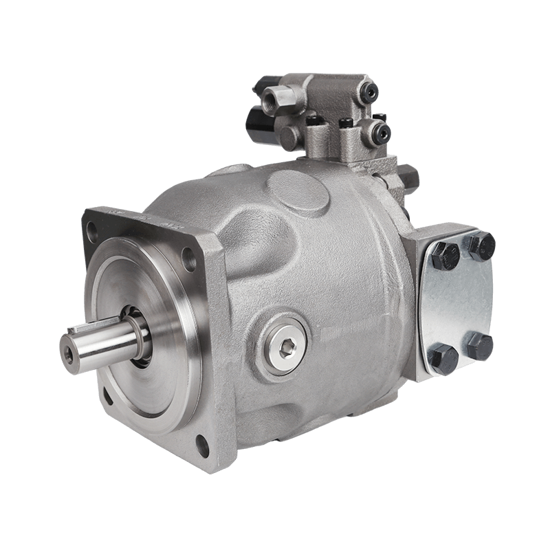
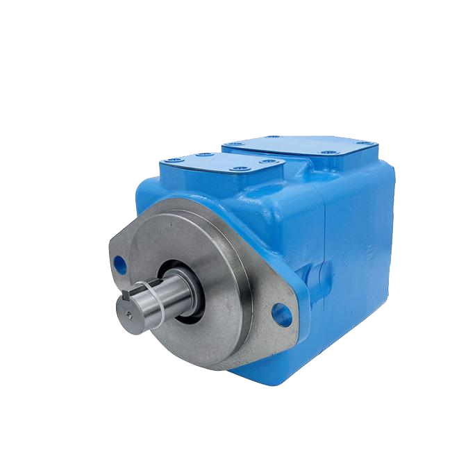
What are the 3 types of hydraulic pumps?
The three main types of hydraulic pumps are gear pumps, vane pumps, and piston pumps. Gear pumps are widely used for their simplicity, durability, and cost efficiency. Vane pumps offer smooth flow and moderate pressure performance, often in industrial systems where low noise is valued. Piston pumps, including axial and radial piston types, are generally selected for high-pressure, high-efficiency, or variable displacement applications. According to Grand View Research, hydraulic equipment demand remains strong in sectors where reliability and force density are mission-critical, and each pump type serves a different performance niche. A gear pump is often the most economical choice for fixed-displacement systems. A vane pump may be preferred where smoothness and moderate pressure are priorities. A piston pump is commonly considered the most efficient hydraulic pump in demanding high-pressure systems, though it is usually more complex and expensive. A 3 stage hydraulic pump discussed in this article is typically based on external gear pump architecture. That makes it attractive for OEMs needing a robust, relatively compact, and application-specific solution without the cost profile of a piston design.