
Hydraulic gear pumps stay important pieces in industrial setups and machines. They move fluid well and build pressure nicely. These positive displacement pumps handle key jobs in heavy equipment, cars, hydraulic presses, and many factory tasks.

Introduction to Hydraulic Gear Pumps
What is a Hydraulic Gear Pump?
A hydraulic gear pump works as a positive displacement unit. It pushes hydraulic fluid through the system to create flow and send power. It gives a steady amount of fluid with each turn of its gears. This makes it great for jobs that need steady pressure and flow. Think of lifting setups, steering parts, and moving heavy gear.
The main idea comes from two gears that fit together — usually one drive gear and one idler gear. They sit close inside a strong case. This setup cuts down leaks. It keeps fluid moving evenly no matter the pressure changes.
Hydraulic gear pumps are known for a few good points:
- Simplicity — few moving pieces so they go together and get fixed easily
- Sturdiness — they handle high pressure and tough spots well
- Efficiency — they give steady output without much trouble
Importance of Hydraulic Systems
Hydraulic systems do a great job sending lots of power through small packages with pressed fluid. This gives exact control and handles big weights easily in different fields.
Main good sides include:
- High power-to-weight ratio so parts stay small but strong
- Precise control that matters in planes, robots, and auto systems
- Reliability even in rough places
- Durability with less fixing than old mechanical ways
Applications of Hydraulic Gear Pumps

Hydraulic gear pumps work in many areas because they last long, stay accurate, and push high-pressure fluid.
| Application Area | Equipment Examples | Key Benefits |
|---|---|---|
| Construction Machinery | Excavators, loaders, bulldozers | Reliable performance in rough conditions, strong cylinder actuation |
| Agricultural Equipment | Tractors, harvesters, sprayers | Consistent flow and pressure for efficient field tasks |
| Industrial Manufacturing | Hydraulic presses, molding machines, assembly lines | Steady pressure for precision operations and automation |
| Material Handling | Forklifts, cranes, aerial platforms | Accurate and secure lifting in warehouses and logistics |
| Marine & Offshore | Ship steering, winches, deck equipment | Durable operation in corrosive marine settings |
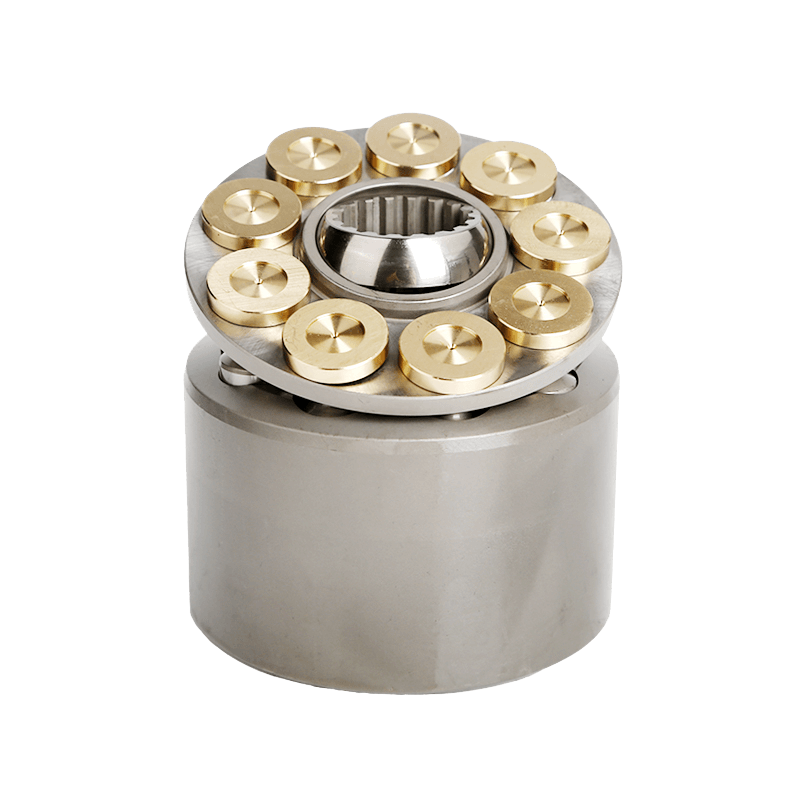
Components of Hydraulic Gear Pumps
Overview of Gear Pump Components
Good fluid movement comes from parts that work together well:
- Gears — hardened steel or bronze alloy external gears (drive and driven) for precise meshing
- Housing — cast iron, aluminum, or steel enclosure providing structural integrity
- Shafts and Bearings — support smooth rotation and connection to power sources
- Seals and Gaskets — elastomer or composite materials resistant to chemicals and temperatures
- Pressure Ports — inlet and outlet designs minimizing losses and ensuring durability
- Relief Valve — safety mechanism redirecting excess flow at preset pressure limits


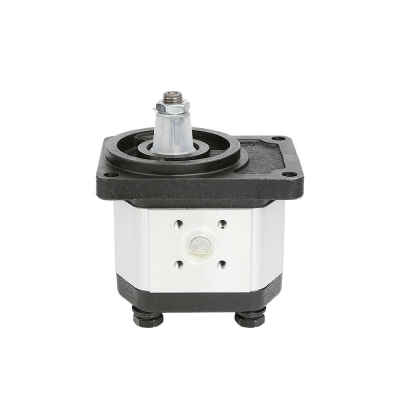
Understanding External Gear Configuration
External gear pumps have two gears that mesh and spin the opposite way inside the housing. Fluid gets caught in spaces between the teeth and the case. Then it moves from the inlet side over to the outlet.
Common specs look like this:
- Operating pressure: 1,000–3,000 PSI
- Efficiency: Often exceeding 90%
- Materials: Hardened steel or advanced composites
- Capabilities: Bi-directional flow and integration with electronic controls
Detailed Breakdown of Internal Components
Housing comes from cast iron, aluminum alloys, or stainless steel. It protects the inside parts under high pressure and hot conditions.
Rotors/Gears get machined carefully into spur or helical shapes. They use hardened steel or composites so they mesh right and move fluid smoothly.
Seals & Bearings often use nitrile rubber, PTFE, or Viton. They pair with bronze or ceramic bearings to keep friction low and make them last longer.
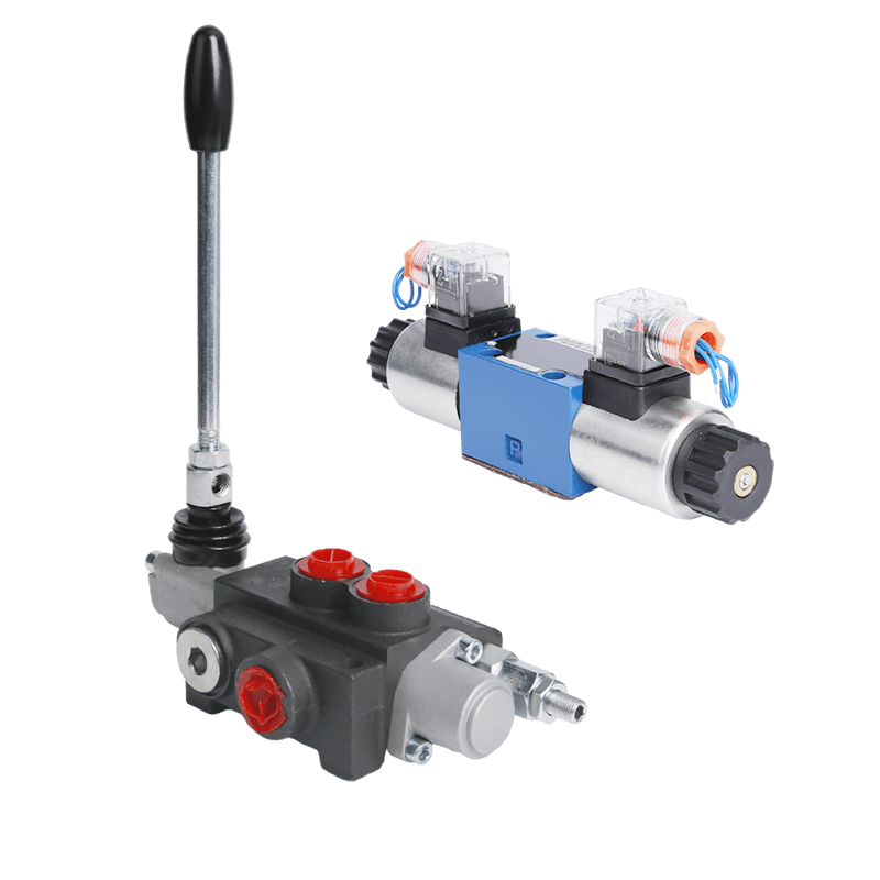
Control Valves can be electrohydraulic or servo types. These allow exact changes to flow and pressure right when needed.
Hydraulic Pump Performance
Factors Influencing Hydraulic Pump Efficiency
Efficiency comes from several things:
- Mechanical efficiency drops from friction in bearings and seals. Better materials and good oil help fix that.
- Volumetric efficiency suffers from inside leaks. Tight fits make it better.
- Hydraulic efficiency links to how thick the fluid is and the temperature.
- Keeping dirt out with good filters matters a lot.
- Smart system design for pressure, flow, and part placement helps too.
Performance Metrics for Gear Pumps
| Metric | Description | Typical Range/Unit | Importance |
|---|---|---|---|
| Flow Rate | Fluid conveyance capacity | GPM or L/min | Determines system throughput |
| Pressure Rating | Maximum safe operating pressure | Up to 3,000+ PSI | Suitability for application demands |
| Volumetric Efficiency | Resistance to leakage | Percentage (%) | Reflects manufacturing precision |
| Power Consumption | Input energy required | kW or HP | Impacts operational costs |
| Temperature Stability | Performance across thermal ranges | °C or °F | Ensures long-term reliability |
| Noise Levels | Acoustic output | Decibels (dB) | Compliance with environmental standards |
Common Issues and Troubleshooting Techniques
Troubleshooting Guide:
- Low Flow Rate: Look for air getting in. Clean the inlet filters. Check the suction line stays solid. Make sure the pump size fits right.
- Noise and Vibration: See if cavitation happens or air leaks exist. Swap out worn bearings. Check shaft alignment. Keep lubrication good.
- Overheating: Check fluid thickness. See if lubrication works well. Watch pressures. Avoid long runs at high pressure.
Types of Hydraulic Pumps
Comparison of Hydraulic Gear Pumps and Other Types
| Pump Type | Pros | Cons | Best For |
|---|---|---|---|
| Gear | Compact, cost-effective | Noisy, moderate efficiency | Moderate pressure applications |
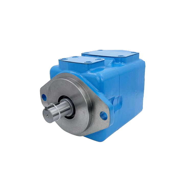
| Vane | Steady flow, efficient | Seal-dependent | Systems requiring smooth delivery |
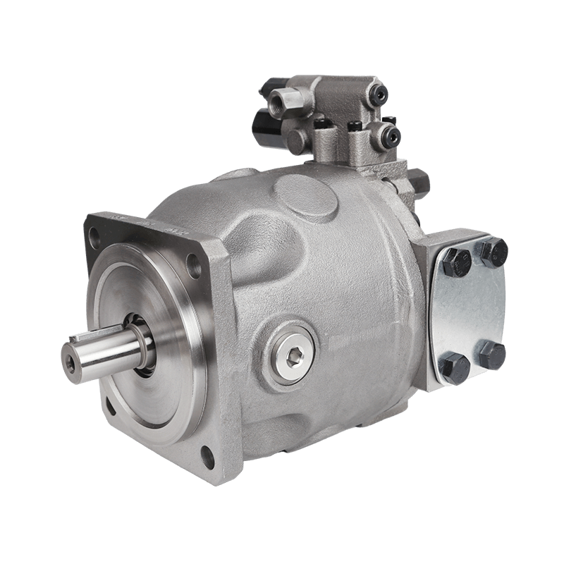
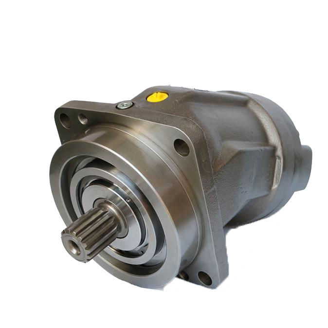
| Piston | High pressure, durable | Higher cost, complex | Demanding high-pressure tasks |
| Screw | High efficiency | Expensive, intricate | High flow/pressure needs |
| Centrifugal | Handles low viscosity | Ineffective for high viscosity | Low-viscosity fluid transfer |
External Gear Pumps vs. Internal Gear Pumps

| Aspect | External Gear | Internal Gear |
|---|---|---|
| Pressure Range | High | Moderate |
| Fluid Viscosity | Medium | High |
| Heat Tolerance | Medium | High |
| Cost | Lower | Higher |
| Size | Compact | Bulkier |
| Flow Direction | Uni/Bi-directional | Bi-directional |
| Use Cases | Fuels, chemicals, hydraulics | Resins, bitumen, precision |
Choosing the Right Hydraulic Pump for Your Application
Picking the right one means looking at:
- Pressure and flow needs for what the system must do
- Fluid traits like thickness and dirt level
- Temperature limits and how heat gets handled
- Space limits in the setup
- Balance of starting cost against long use
- Extra wants like two-way flow or smart controls
Real-World Applications of Hydraulic Gear Pumps
Case Studies in Industrial Settings
Case Study 1: Enhancing Efficiency in Manufacturing Lines An automotive assembly place fixed uneven hydraulic work. They switched to strong external gear pumps. This brought 23% better efficiency, less stopped time, and cheaper upkeep.
Case Study 2: Agricultural Sector Optimization Tractor makers added bi-directional gear pumps. They got 15% better efficiency, 30% longer life, and fewer breaks in work.
Case Study 3: Hydraulic Systems for Marine Operations Corrosion-resistant internal gear pumps went into fishing boat winches. They had 35% fewer breakdowns, better planning, and big savings on fixes.
Future Trends in Hydraulic Pump Technology
New steps forward cover:
- Electro-hydraulic mixing for smart digital control
- Light composites for planes and auto work
- Designs that work with eco-friendly fluids
- Sensors built in for guessing when maintenance comes
- Modular setups for easy changes
Frequently Asked Questions (FAQ)
Q: What is a hydraulic gear pump diagram?
A: A hydraulic gear pump diagram shows the parts, how it runs, and where fluid flows inside a gear pump. It helps people understand gear setup and fluid movement in systems.
Q: How does a hydraulic gear pump work?
A: It makes a vacuum at the inlet with gear meshing to pull fluid in. Then rotation carries it to the outlet. This creates steady flow for hydraulic jobs.
Q: What are the types of hydraulic pumps?
A: Main kinds include gear, vane, piston, and screw pumps. Each fits certain needs for turning energy in hydraulic ways.
Q: What distinguishes fixed displacement and variable displacement pumps?
A: Fixed displacement pumps keep flow the same no matter pressure. Variable ones change output to match what the system needs. This boosts efficiency.
Q: Why is volumetric efficiency important in hydraulic gear pumps?
A: It shows how well input power turns into hydraulic output with little waste. This affects how well it runs and costs to use.
Q: How is an external gear pump different from an internal one?
A: External gear pumps have meshing gears outside the case. Internal ones put one gear inside another. They give different flow traits and suction perks.
Ready to Source Reliable Hydraulic Gear Pumps?
POOCCA stands as a leading manufacturer, supplier, and factory specializing in high-quality hydraulic gear pumps, including external and internal types compatible with brands such as Rexroth, Parker, Shimadzu, Marzocchi, Casappa, Sunny, and more. With over 20 years of experience, ISO-certified production, extensive stock, competitive factory-direct pricing, 12-month warranties, and global exports to over 120 countries, POOCCA delivers customizable solutions, rapid delivery, and comprehensive technical support for industrial, construction, agricultural, and marine applications. Contact the POOCCA team today to discuss specifications, request quotes, or explore OEM replacements for optimized hydraulic system performance. Reach out via sales channels for expert assistance in selecting the ideal gear pump solution.