 English
 Russian
 Arabic
 Indonesian
 Turkish
 Vietnamese
 Polish
 German
 Malay
 Thai
 Kazakh
 Spanish
 Chinese (Simplified)
 Korean
 Italian
 Azerbaijani
 Dutch
 French
 Romanian
 Portuguese
 Hindi


Menu
Close
Menu
Close


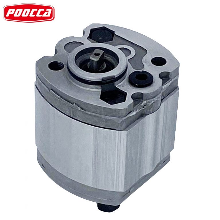
The HG00-10-08-01R-VSC double gear pump has two fixed-displacement internal gear sections: 10.2 cc/rev at the front and 8.2 cc/rev at the rear. This double hydraulic pump uses a clockwise 9-tooth splined drive, a shared suction inlet and two separate outlets.
Use these catalogue dimensions to review the drive and port layout before ordering. For a replacement, compare the full nameplate code and the drawing for the quoted unit with the parts already installed on the machine.
| Parameter | Catalogue reference |
|---|---|
| Model designation | HG00-10-08-01R-VSC |
| Pump type | Fixed-displacement tandem internal gear pump, HG0 front and rear sections |
| Geometric displacement | Front 10.2 cm³/rev, rear 8.2 cm³/rev |
| Input rotation | Clockwise, viewed from the shaft end (R) |
| Drive shaft | Spline (S), ANSI B92.1, 9 teeth, 16/32 DP, 30° pressure angle |
| Mounting flange | SAE two-bolt (C), Ø82.55 mm pilot and 106.4 ± 0.2 mm mounting-hole centre distance on the VSC drawing |
| Installation dimensions | Drawing dimensions A1 56 mm, A2 119.5 mm, A3 115.5 mm, A4 224.3 mm for front size 10 and rear size 08 |
| Shared suction port | Ø32 mm bore, 4 × M10 mounting threads, 17 mm deep, with 58.7 × 30.2 mm bolt spacing |
| Pressure outlets | Two separate flange outlets. Confirm the flange dimensions and outlet positions on the quoted drawing. |
| Seal code | V, fluororubber (FKM) |
| Rated pressure reference | 315 bar (31.5 MPa) for each HG0 single-pump size in the catalogue. Confirm the combined-load limit for the tandem assembly. |
| Short-duration pressure reference | 350 bar (35 MPa) for 10 seconds for each HG0 single-pump size. Confirm the applicable limits for the quoted assembly and duty cycle. |
| Speed reference | 600–3,000 rpm for the corresponding HG0 single-pump sizes. Confirm tandem operating limits at the intended load and inlet conditions. |
| Assembled weight | Confirm the net pump weight and packed shipping weight on the quotation. |
The pressure and speed figures are reference data for the individual HG0 sections. Share both circuits’ pressure, speed and duty cycle so the tandem pump and drive can be reviewed for simultaneous loading.
At 1,500 rpm the two sections have calculated theoretical flows of 15.3 L/min at the front and 12.3 L/min at the rear. Use these figures for initial sizing. Actual flow depends on pressure, oil viscosity and volumetric losses. If both outlets work at once, share the flow and pressure required at each outlet and the operating speed at that point in the cycle.
| Code | Meaning |
|---|---|
| HG | Internal gear pump family |
| 00 | HG0 frame at the front and rear |
| 10 / 08 | Front and rear displacement size codes, in that order |
| 01 / R | Design code 01 and clockwise input rotation |
| V / S / C | Fluororubber seals, splined shaft and SAE two-bolt flange |
VSC and VPC use different drive shafts. In the HG00 drawing, VSC uses a 9-tooth spline and VPC uses a keyed shaft. If you are replacing a pump with a keyway, send a shaft photo and the complete nameplate code so the coupling can be checked against the quoted version.
For a fit check, provide the pilot diameter, mounting-hole spacing, coupling type, port flange dimensions and outlet orientation. A photo showing the drive end and both sides of the assembly helps identify which fittings, adapters and hose clearances need to be checked. Use the original front and rear displacement order when requesting a replacement for two separate circuits.

For an installation with tight clearances, ask for the approved drawing for the exact model and both outlets. Share the model number, coupling dimensions and the available space around the flange and hoses.
Where a machine uses two hydraulic circuits with different flow requirements, the tandem configuration gives each circuit its own pressure outlet. Share which functions run simultaneously and their flow and pressure requirements when you request selection support.
For an existing power unit, check the motor adapter, coupling, suction connection and pressure flange positions. A drawing of the cabinet or pump mounting area helps confirm whether the replacement can use the existing pipework.
If the pump is driven by a variable-speed motor, provide the speed range during approach, working and holding phases. The shared suction inlet needs to be reviewed for the combined flow demand of both sections.
The size codes are 10 at the front and 08 at the rear. The HG0 section table lists actual geometric displacements of 10.2 and 8.2 cm³/rev respectively.
The HG00 VSC drawing specifies a 9-tooth spline to ANSI B92.1, 16/32 DP with a 30° pressure angle. The keyed-shaft drawing is under the VPC suffix.
The catalogue lists 315 bar for each HG0 section as an individual reference. Provide the maximum load on each outlet and the time the two loads overlap so the assembled pump, drive and coupling can be reviewed for your duty cycle.
Send the complete pump code, a readable nameplate photo, photos of the shaft and ports, the quantity and the delivery destination. If the original model code is incomplete, include the mounting and coupling dimensions.
Request a drawing for the exact configuration along with lead time, package dimensions, gross weight and warranty terms. Include any inspection or documentation requirements in your enquiry.
Use these catalogue dimensions to review the drive and port layout before ordering. For a replacement, compare the full nameplate code and the drawing for the quoted unit with the parts already installed on the machine.
| Parameter | Catalogue reference |
|---|---|
| Model designation | HG00-10-08-01R-VSC |
| Pump type | Fixed-displacement tandem internal gear pump, HG0 front and rear sections |
| Geometric displacement | Front 10.2 cm³/rev, rear 8.2 cm³/rev |
| Input rotation | Clockwise, viewed from the shaft end (R) |
| Drive shaft | Spline (S), ANSI B92.1, 9 teeth, 16/32 DP, 30° pressure angle |
| Mounting flange | SAE two-bolt (C), Ø82.55 mm pilot and 106.4 ± 0.2 mm mounting-hole centre distance on the VSC drawing |
| Installation dimensions | Drawing dimensions A1 56 mm, A2 119.5 mm, A3 115.5 mm, A4 224.3 mm for front size 10 and rear size 08 |
| Shared suction port | Ø32 mm bore, 4 × M10 mounting threads, 17 mm deep, with 58.7 × 30.2 mm bolt spacing |
| Pressure outlets | Two separate flange outlets. Confirm the flange dimensions and outlet positions on the quoted drawing. |
| Seal code | V, fluororubber (FKM) |
| Rated pressure reference | 315 bar (31.5 MPa) for each HG0 single-pump size in the catalogue. Confirm the combined-load limit for the tandem assembly. |
| Short-duration pressure reference | 350 bar (35 MPa) for 10 seconds for each HG0 single-pump size. Confirm the applicable limits for the quoted assembly and duty cycle. |
| Speed reference | 600–3,000 rpm for the corresponding HG0 single-pump sizes. Confirm tandem operating limits at the intended load and inlet conditions. |
| Assembled weight | Confirm the net pump weight and packed shipping weight on the quotation. |
The pressure and speed figures are reference data for the individual HG0 sections. Share both circuits’ pressure, speed and duty cycle so the tandem pump and drive can be reviewed for simultaneous loading.
At 1,500 rpm the two sections have calculated theoretical flows of 15.3 L/min at the front and 12.3 L/min at the rear. Use these figures for initial sizing. Actual flow depends on pressure, oil viscosity and volumetric losses. If both outlets work at once, share the flow and pressure required at each outlet and the operating speed at that point in the cycle.
| Code | Meaning |
|---|---|
| HG | Internal gear pump family |
| 00 | HG0 frame at the front and rear |
| 10 / 08 | Front and rear displacement size codes, in that order |
| 01 / R | Design code 01 and clockwise input rotation |
| V / S / C | Fluororubber seals, splined shaft and SAE two-bolt flange |
VSC and VPC use different drive shafts. In the HG00 drawing, VSC uses a 9-tooth spline and VPC uses a keyed shaft. If you are replacing a pump with a keyway, send a shaft photo and the complete nameplate code so the coupling can be checked against the quoted version.
For a fit check, provide the pilot diameter, mounting-hole spacing, coupling type, port flange dimensions and outlet orientation. A photo showing the drive end and both sides of the assembly helps identify which fittings, adapters and hose clearances need to be checked. Use the original front and rear displacement order when requesting a replacement for two separate circuits.
For an installation with tight clearances, ask for the approved drawing for the exact model and both outlets. Share the model number, coupling dimensions and the available space around the flange and hoses.
Where a machine uses two hydraulic circuits with different flow requirements, the tandem configuration gives each circuit its own pressure outlet. Share which functions run simultaneously and their flow and pressure requirements when you request selection support.
For an existing power unit, check the motor adapter, coupling, suction connection and pressure flange positions. A drawing of the cabinet or pump mounting area helps confirm whether the replacement can use the existing pipework.
If the pump is driven by a variable-speed motor, provide the speed range during approach, working and holding phases. The shared suction inlet needs to be reviewed for the combined flow demand of both sections.
The size codes are 10 at the front and 08 at the rear. The HG0 section table lists actual geometric displacements of 10.2 and 8.2 cm³/rev respectively.
The HG00 VSC drawing specifies a 9-tooth spline to ANSI B92.1, 16/32 DP with a 30° pressure angle. The keyed-shaft drawing is under the VPC suffix.
The catalogue lists 315 bar for each HG0 section as an individual reference. Provide the maximum load on each outlet and the time the two loads overlap so the assembled pump, drive and coupling can be reviewed for your duty cycle.
Send the complete pump code, a readable nameplate photo, photos of the shaft and ports, the quantity and the delivery destination. If the original model code is incomplete, include the mounting and coupling dimensions.
Request a drawing for the exact configuration along with lead time, package dimensions, gross weight and warranty terms. Include any inspection or documentation requirements in your enquiry.
Welcome to contact us using WeChat
Welcome to contact us via whatsapp