Hydraulic Pumps & Motors
Hydraulic motors are crucial components in fluid power systems, converting hydraulic energy into mechanical motion. While hydraulic pumps generate flow to transmit energy, hydraulic motors receive this flow and transform it into torque and rotation. These systems are widely used in mobile equipment, industrial machinery, and marine applications due to their ability to deliver high torque at low speeds.

Fundamentals of Hydraulic Motors
Rugged hydraulic motors transform fluid energy into rotary mechanical power, which typically is applied to a load via shaft. All types of hydraulic motors have common design features: a driving surface area subject to pressure differential; a way of timing the porting of pressure fluid to the pressure surface to achieve continuous rotation; and a mechanical connection between the surface area and an output shaft.
Motor displacement refers to the volume of fluid required to turn the motor output shaft through one revolution. It can be fixed or variable. A fixed-displacement motor provides constant torque. Controlling the amount of input flow into the motor varies the speed. A variable-displacement motor provides variable torque and variable speed.
Torque output is expressed in inch-pounds or foot-pounds. It is a function of system pressure and motor displacement. There are several types of torque: breakaway torque (to start motion), running torque (to maintain motion), and starting torque (initial motion capability). Running torque considers a motor’s inefficiency and is a percentage of its theoretical torque.
Efficiency metrics include mechanical efficiency (actual vs theoretical torque) and volumetric efficiency (actual vs theoretical flow). Motor speed depends on displacement and flow rate, while slippage refers to internal leakage that reduces performance.
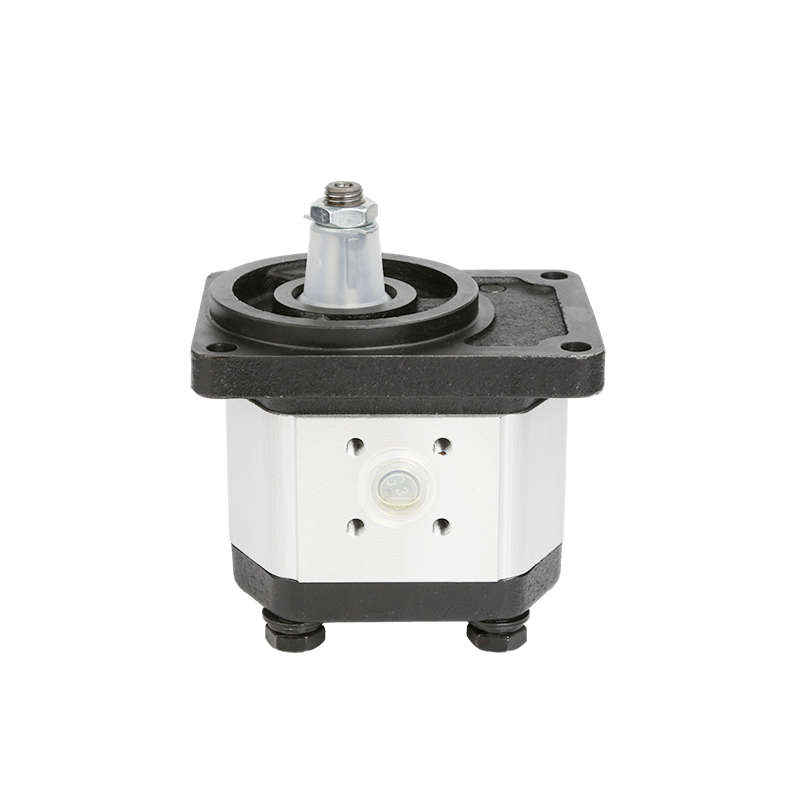
Gear Motors
Gear motors are among the simplest hydraulic motors. External gear motors consist of a pair of matched gears enclosed in one housing. Pressure fluid enters the housing at a point where the gears mesh. It forces the gears to rotate and follows the path of least resistance around the periphery of the housing.
Internal gear motors like gerotor types feature an inner gear with one fewer tooth than its outer counterpart. When pressure fluid is introduced into the motor, both gears rotate. The design ensures smooth operation with minimal pressure ripple.
Orbiting gerotor motors use a stationary outer gear and an orbiting inner rotor. The commutator or valve plate always provides pressure fluid and a passageway to tank to the proper spaces between the two gears. Roller-vane variations reduce wear by incorporating rolling vanes instead of direct contact surfaces.
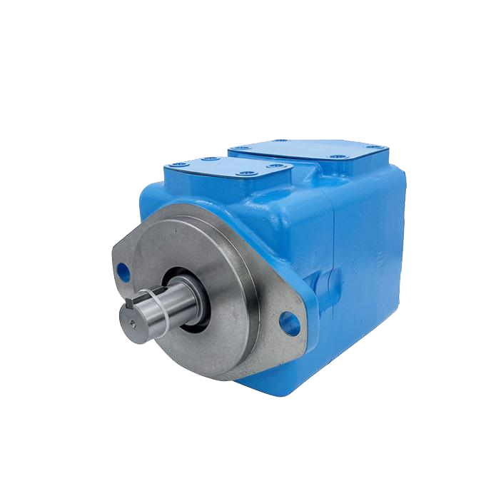
Vane Motors
Vane motors have a slotted rotor mounted on a driveshaft that is driven by the rotor. Vanes move radially within slots to maintain contact with an eccentric cam ring. Pressure fluid entering at inlet ports moves the rotor counterclockwise. If pressure were introduced at outlet ports, it would turn the motor clockwise.
These motors are cost-effective but typically offer lower efficiencies compared to piston designs. The service life of a vane motor usually is shorter than that of a piston motor, though. They are suitable for moderate performance applications with displacements up to 756 in³/rev.
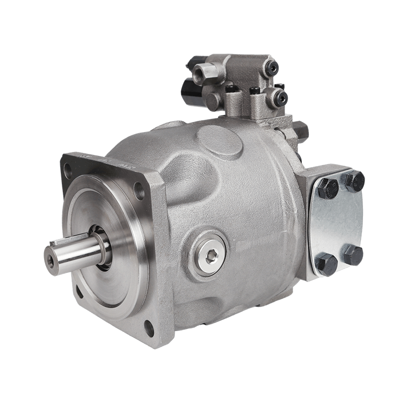
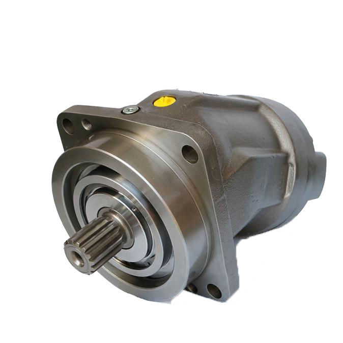
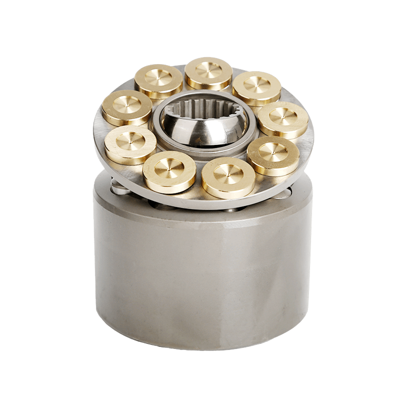
Piston-Type Motors
Radial-piston motors operate using pistons arranged radially around a cylinder barrel. Pressure fluid flows through a pintle in the center.The pistons push against the thrust ring and the reaction forces rotate the barrel. These designs offer excellent low-speed performance with high efficiency but come at higher initial costs due to precision manufacturing.
Axial-piston motors differ by aligning pistons axially along a cylinder block centered on or angled from the drive shaft. Inline-piston motors generate torque through pressure exerted on, reciprocating in a cylinder block. Variable-displacement models adjust swashplate angles for dynamic control over speed and torque.
Bent-axis piston designs mount cylinder blocks at an angle relative to drive shafts. Speed and torque change with changes in angle from maximum displacement/torque at about 30° to minimum at about 7.5°.
Other Designs
Rotary abutment motors use rotating abutments that pass vanes while maintaining seals via timing gears. Torque is transmitted directly from the fluid to the rotor and from the rotor to the shaft.
Screw motors operate like reversed pumps using meshing screws within close-tolerance housings. Differential pressure acting on thread areas develops motor torque, providing quiet, vibration-free operation.
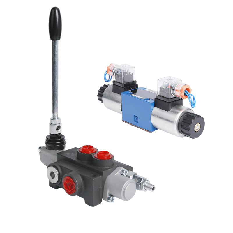
Selecting a Hydraulic Motor
Choosing among different hydraulic motors depends on application needs such as horsepower, expected life span, operating conditions, and cost constraints. The application dictates required horsepower and speed range, although actual speed/torque may vary while maintaining horsepower.
Once type of fluid is determined, selection of size is based on expected life and economics. Operating below rated capacity can significantly extend service life.
Sizing a Hydraulic Motor
Proper sizing ensures optimal performance under specified conditions. For example, if 5 hp at 3,000 rpm is needed with 2,900 psi differential:
T = (63,0252 × hp)/N, where T = 105 lb-in.
Then calculate displacement:
D = 2π T ÷ ∆PeM. With eM = 88%, D = 0.258 in³/rev.
Required flow:
Q = DN/231eV. With eV = 93%, Q = 3.6 gpm.
Efficiency drops near extreme speeds or pressures due to internal losses characteristic in all fluid-driven systems.
Hydraulic Motor Malfunctions

Most issues arise from poor maintenance or unsuitable operation conditions. The motor must have clean fluid; proper quality/viscosity; poor maintenance runs close second in causing major problems.
Common faults include leaks allowing contamination or air ingress, improper installation leading to misalignment, or failure analysis neglect—leading to repeated breakdowns.
Exceeding limits promotes failure: excessive pressure causes heat/slippage; excessive speed wears bearings; excessive load stresses shafts; excessive temperature thins oil reducing lubrication efficiency.
Partner with POOCCA for High-Performance Hydraulic Motors
POOCCA is your trusted partner when it comes to sourcing reliable and efficient hydraulic solutions. We have up to 1,600 product categories, mainly engaged in gear pumps, piston pumps, vane pumps, motors, hydraulic accessories, hydraulic valves, etc.
Our lineup includes advanced models like the Poclain MS MSE series which deliver high productivity with new design achieving maximum speed without additional voltage drop. These units also help reduce machine consumption and total cost of ownership.
Whether you’re upgrading existing systems or designing new applications from scratch—our team provides expert guidance every step of the way. Contact POOCCA for instant quote now.
FAQ
What is a hydraulic motor?
A hydraulic motor converts pressurized fluid into mechanical rotation used for driving machinery components like wheels or conveyor belts.
How do I choose between gear vs piston vs vane motor?
Gear motors suit simple applications; vane offers smoother operation; piston types deliver high torque/power needed in heavy-duty environments.
What causes most failures in hydraulic motors?
Common issues include contamination-induced wear/scoring inside chambers or seals failing due to excessive temperature/pressure fluctuations.
What makes POOCCA’s products stand out?
High-flow hydraulic motors designed to increase machine performance and reduce fuel consumption. They also feature advanced engineering that ensures reliability under extreme conditions while minimizing operational costs over time.